subatomic nano positioning flexure stage
· research, electronics
For my senior design project, Im working on developing the mechatronics for a really high precision positioning stage. The idea of the project is to study the parasitic dynamic errors that occur in these really high precision flexure stages. In order to do that, however, we needed a stage to test with.
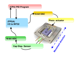
The lab had an extra lion precision capacitance gage system that we were able to use for testing, along with an extra piezo driver. So for actuation, we used a PZT stack actuator and closed the loop with said capacitance gage. The control system basically just consisted of a PI controller, running at around 50 kHz with an ADS8681 16 bit ADC and a Pmod DA3 DAC. the dac output goes into a 150V PZT amplifier. funny enough, since this is an analog signal amplifier, you can technically hook it up to an aux audio output. enjoy this video of me scrolling through youtube shorts with the audio playing through the flexure stage:
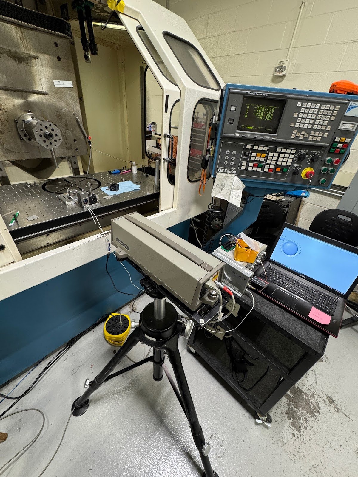
After calibrating the capacitance gage with the shop Agilent interferometer, I found the system to have a per-bit resolution of around 300 picometers!
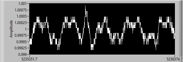
isolating its environment and analyzing the system at rest showed around +/-600 pm positioning accuracy, obviously making the large assumption there are no changes occuring between the nominal capacitance probe and carriage face distance :)
I think this qualifies as a nano positioning stage. The next plan is to develop the parasitic motion sensing system, now that this works. the project sponsor was interested in seeing how the dynamics of the system change with a ring stack versus a solid square stack pzt actuator. we bought some of these and to assemble them i made a fixture for assembling these actuators, as they need to be concentrically constrained.
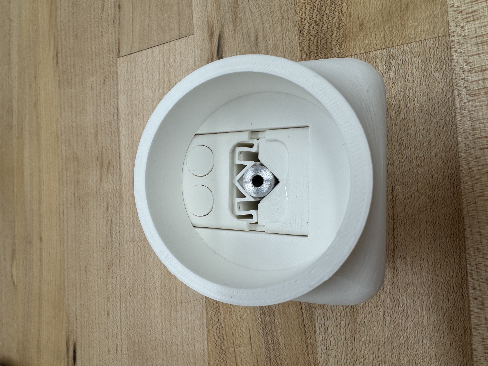
although constraining these actuators through the center is technically ideal, i did not want to risk getting a fixture stuck inside with the epoxy inside. for this reason i decided to constrain the actuator on the outside, using a 3d printed flexure jig. the idea was to machine a reference 'actuator' with the geometry of a finished fully assembled actuator, put it inside a flexure based jig, pour superglue inside to hold the flexures in that place, then assemble the actuator inside the deformed cavity that was molded around the reference. this went quite well on the first go with an aluminum test actuator, qualitatively at least. you cannot really see any misalignment from photos alone, which was my indicator for 'good enough'.
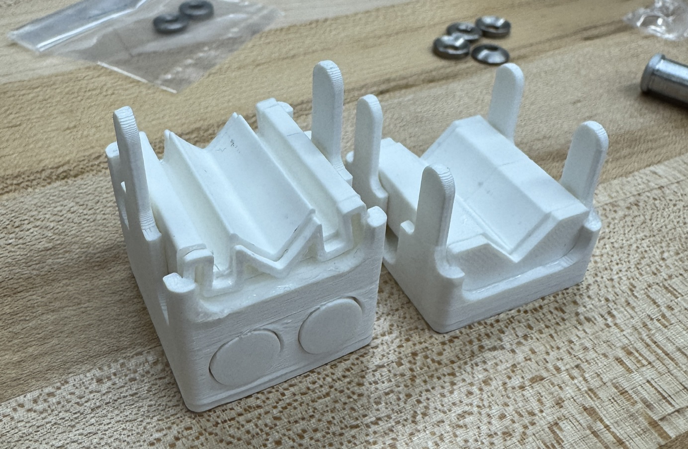
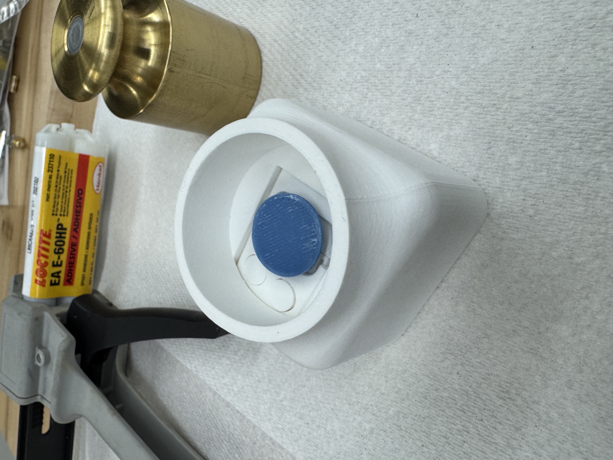
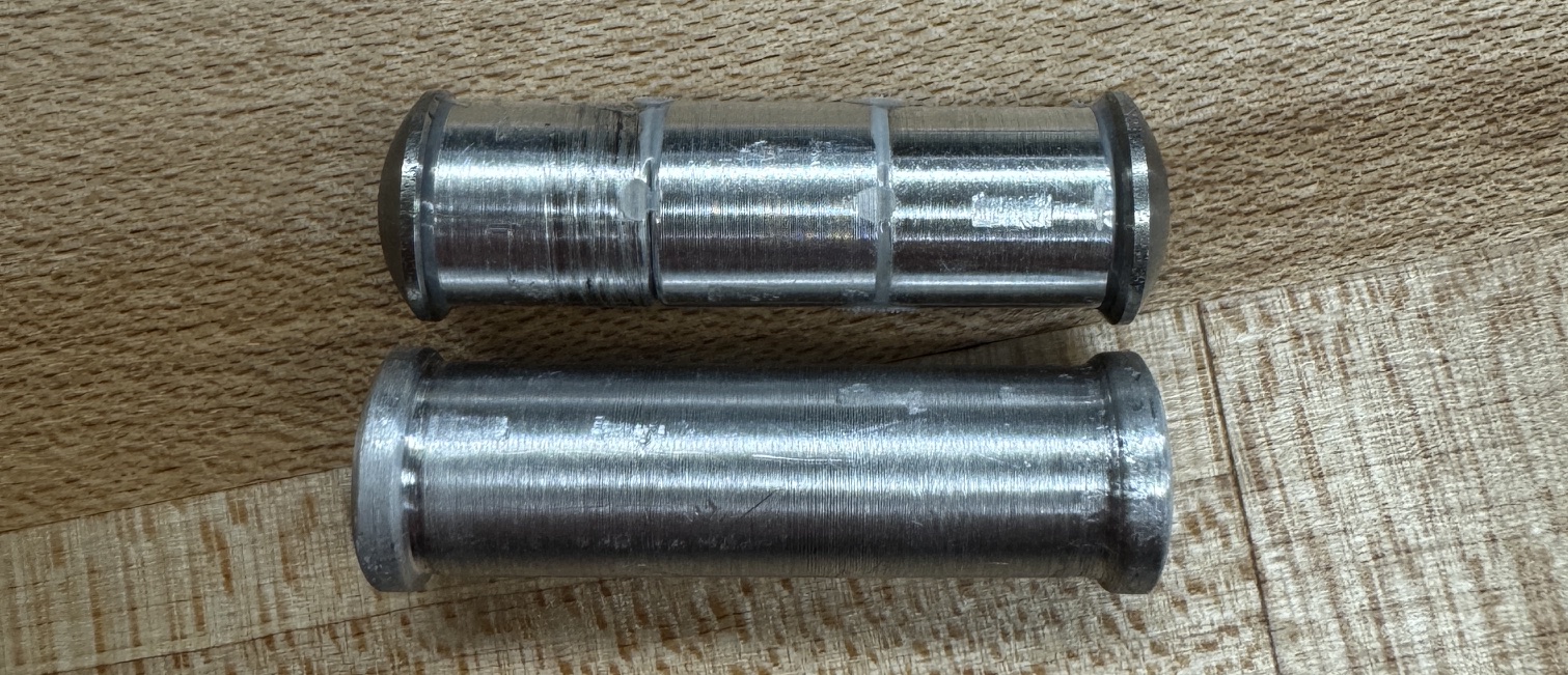
for the actual actuator, it worked the same way. with this ready to go, instrumentation is ready for development!